Systems Analysis & Design
- Media:System_analysis-Model_a_Video_Rental_Machine_using_UM.pdf
- Media:System_analysis-Model_an_ATM_Machine_using_UM.pdf
Contents
- 1 UML/CASE tools
- 2 UML
- 3 Agile software development
- 4 A student guide to object-oriented development
UML/CASE tools
UML/CASE tools such as: Visual Paradigm, Dia, ARGO or Draw.io
Visual Paradigm
https://www.visual-paradigm.com/
https://en.wikipedia.org/wiki/Visual_Paradigm
Visual Paradigm (VP-UML) is a UML CASE Tool supporting UML 2, SysML and Business Process Modeling Notation (BPMN) from the Object Management Group (OMG).
Visual Paradigm User's Guide: https://www.visual-paradigm.com/support/documents/vpuserguide.jsp
Installation
Link to download Visual Pardigm community edition (free): http://www.visual-paradigm.com/download/community.jsp
- El link anterior descarga un archivo .sh. Sólo debemos ejecutar dicho archivo y seguir el instalador GUI:
./Visual_Paradigm_CE_15_1_20180931_Linux64.sh
- Visual Paradigm Community Edition is available for free for non-commercial use. Para activarlo, el programa solicitará un email al cual enviará un activation code.
UML
Class Diagram
https://www.visual-paradigm.com/guide/uml-unified-modeling-language/uml-class-diagram-tutorial/
https://www.visual-paradigm.com/features/uml-tool/
https://www.visual-paradigm.com/guide/uml-unified-modeling-language/what-is-class-diagram/
https://forums.visual-paradigm.com/t/how-to-define-usages-of-static-classes-in-class-diagram/12035
https://forums.visual-paradigm.com/t/how-to-specify-static-attributes/7681
https://www.visual-paradigm.com/support/documents/vpuserguide/94/2576/7190_drawingclass.html
https://www.visual-paradigm.com/VPGallery/diagrams/Class.html
https://www.visual-paradigm.com/support/documents/vpuserguide/1283/27/85356_showingvisib.html
https://www.visual-paradigm.com/support/documents/vpuserguide/1283/29/6058_umlnote.html
https://forums.visual-paradigm.com/t/nested-class-question/10795
https://forums.visual-paradigm.com/t/multiple-inner-classes-how/11928
Agile software development
https://en.wikipedia.org/wiki/Agile_software_development
Al parecer éste es el approach que se usan en las empresas de desarrollo de softwares. De allí la importancia de esta sección.
Agile software development describes an approach to software development under which requirements and solutions evolve through the collaborative effort of self-organizing and cross-functional teams and their customer(s)/end user(s).
It advocates adaptive planning, evolutionary development, early delivery, and continual improvement, and it encourages rapid and flexible response to change.
The term Adaptive planning means: Welcome changing requirements, even in late development... being able to adapt to changing requirements if necessary.
Agile software development methods or frameworks
https://en.wikipedia.org/wiki/Agile_software_development
No estoy seguro de cual es el término que se usa aquí. Al parecer se habla de Methods or Frameworks.
Popular agile software development methos/frameworks include
Scrum
Scrum is an agile framework for managing work with an emphasis on software development. It is designed for teams of three to nine developers who break their work into actions that can be completed within timeboxed iterations, called Sprints (30 days or less) and track progress and re-plan in 15-minute stand-up meetings, called Daily Scrums.
Daily Scrums:
Every day, a 15 min meeting is held, and the Scrum Master ask the 3 questions:
- What have you accomplished since the last meeting.
- Are there any obstacles in the way of meeting your goal.
- What will you accomplish before the next meeting.
Sprints:
- 30 days or less.
- New functionality is demostrated at the end of each sprint.
Extreme programming (XP)
It's a software development methodology which is intended to improve software quality and responsiveness to changing customer requirements. As a type of agile software development, it advocates frequent "releases" in short development cycles, which is intended to improve productivity and introduce checkpoints at which new customer requirements can be adopted.
XP consists of:
- Planning:
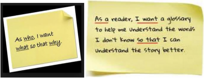
- User stories: Users develop a set of stories to describe what the system needs to do.
- Stand-up meetings
- Small releases
- Design:
- Simple designs: "KISS" and design continuously
- Stresses not to add functionalities until it is needed
- Coding:
- User is always available for feedback
- Developers work in pairs on designing, coding and testing.
- The code is written to an agreed standard.
- Testing:
- Tests are written before the code (before solutions are implemented).
User stories
User stories are one of the primary development artefacts for Scrum and Extreme Programming (XP) project teams. A user story is a very high-level definition of a requirement, containing just enough information so that the developers can produce a reasonable estimate of the effort to implement it.
Agile software development practices
Cada uno de los Methos or Frameworks usa algunas de estás Practices
Cross-functional team
A cross-functional team is a group of people with different functional expertise working toward a common goal. It may include people from finance, marketing, operations, and human resources departments. Typically, it includes employees from all levels of an organization. Members may also come from outside an organization (in particular, from suppliers, key customers, or consultants).
Cross-functional teams often function as self-directed teams assigned to a specific task which calls for the input and expertise of numerous departments.
Timeboxing
In time management, timeboxing allocates a fixed time-period, called a time box, to each planned activity. Several project management approaches use timeboxing. It is also used for individual use to address personal tasks in a smaller time frame. It often involves having deliverables and deadlines, which will improve the productivity of the user.
Pair programming
Sometimes referred to as peer programming, is an agile software development technique in which two programmers work as a pair together on one workstation. One, the driver, writes code while the other, the observer, pointer or navigator, reviews each line of code as it is typed in. The two programmers switch roles frequently.
While reviewing, the observer also considers the "strategic" direction of the work, coming up with ideas for improvements and likely future problems to address. This frees the driver to focus all of his or her attention on the "tactical" aspects of completing the current task, using the observer as a safety net and guide.
User story
A student guide to object-oriented development
Media:A_student_guide_to_object_oriented_development-Carol_Britton-Jill_Doake.pdf
En este curso nos vamos a baser en este libro: «A student guide to object-oriented development». The book describes how a software system is developed using an object-oriented approach. Para esto, el libro describe el caso de un small business, «the Wheels bike hire company».
The Wheels bike hire company: The case study which is used as the basis for examples and exercises in this book is a typical bicycle hire shop.
Como mencionamos, the approach used is object-orientation, which means that the whole development process is based round the object - a thing or concept that initially represents something in the real world and eventually ends up as a component of the system code. An object-oriented system is made up of objects that collaborate to achieve the required functionality, what the system has to do.
There are two websites for the book, which can be found at:
- One for students: http://books.elsevier.com/companions/o75o661232
- And one for lecturers: http://books.elsevier.com/manualsprotected/0750661232
These sites contain further models for the second case study, a complete set of lecture slides, electronic copy of the code and multiple choice questions for topics covered in the book. There is also a revision notes section that will be helpful as an aide-m6moire for students who are studying for exams.
The traditional system life cycle
When undertaking any large project, it is important to have some kind of framework in order to help identify milestones, structure activities and monitor deliverables.
A life cycle provides a high-level representation of the stages that a development project must go through to produce a successful system.
In software system development, a framework has traditionally been known as a system life cycle model. Although life cycle models have been around for a long time, there is still no general agreement about the precise stages in the development process, the activities that take place at any particular stage, or what is produced at the end of it. This is hardly surprising, since factors such as the type of system being built, the software being used, the timescales and the development environment will all influence decisions about the detailed stages of a project.
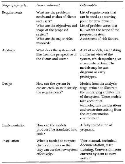
However, at a higher level, there is agreement that there are certain life cycle stages that all projects must go through in order to reach a successful completion. Historically these stages have been referred to as:
- Requirements,
- Analysis,
- Design,
- Implementation
- Installation.
Each stage is concerned with particular issues and produces a set of outputs or deliverables:
Traditional life cycle models
Over the years there have been a number of life cycle models based on the development stages outlined in Table 1.2. In this section we briefly introduce some of the most widely used models:
- Waterfall.
- V-model.
- Spiral.
- Prototyping.
- Iterative development.
- Incremental development.
The object-oriented approach
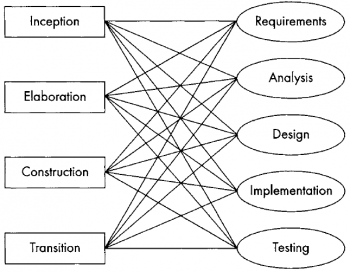
One of the differences that is immediately obvious between traditional life cycle models and the object-oriented approach is the way that the various stages are named. In traditional models the names, such as 'analysis' or 'implementation', reflect the activities that are intended to be carried out in that stage. In object orientation, however, a clear distinction is made between the activities and the stages (generally referred to as phases) of development. The phases in object-oriented development are known as inception, elaboration, construction and transition, indicating the state of the system, rather than what happens at that point in development.
- Inception: it covers the initial work required to set up and agree terms for the project. It includes establishing the business case for the project, incorporating basic risk assessment and the scope of the system that is to be developed.
- Elaboration: it deals with putting the basic architecture of the system in place and agreeing a plan for construction. During this phase a design is produced that shows that the system can be developed within the agreed constraints of time and cost.
- Construction: it involves a series of iterations covering the bulk of the work on building the system; it ends with the beta release of the system, which means that it still has to undergo rigorous testing.
- Transition: covers the processes involved in transferring the system to the clients and users. This includes sorting out errors and problems that have arisen during the development process.
Instead of the traditional high-level system life cycle, the object-oriented approach to development views the relationships between workflows and phases of development rather like the spider's web in the following figure, where any phase may involve all workflows, and a workflow may be carried out during any phase.
The Rational Unified Process (RUP)
A life cycle provides a high-level representation of the stages that a development project must go through to produce a successful system, but it does not attempt to dictate how this should be achieved, nor does it describe the activities that should be carried out at each stage. A development method, on the other hand, is much more prescriptive, often setting down in detail the tasks, responsibilities, processes, prerequisites, deliverables and milestones for each stage of the project.
Over the past decade, there have been a number of object-oriented development methods, such as Responsibility-Driven Design (Wirfs-Brock et al., 199o ), Object Modelling Technique (Rumbaugh et al., 1991) and Open (Graham et al., 1998 ).
Nowadays, almost all object-oriented projects use the Unified Modelling Language as the principal tool in their development process. Use of the UML has been approved by the Object Management Group (OMG), which controls issues of standardization in this area. However, UML is simply a notation or language for development; it is not in itself a development method and does not include detailed instructions on how it should be used in a project.
The creators of the UML, Ivar Jacobson, Grady Booch and James Rumbaugh, have proposed a generic object-oriented development method in their book The Unified Software Development Process (Jacobson et al., 1999) and this generic method has been adopted and marketed by the Rational Corporation under the name of the Rational Unified Process (RUP). RUP incorporates not only modelling techniques from the UML, but also guidelines, templates and tools to ensure effective and successful development of software systems. The tools offered by RUP allow a large part of the development process to be automated, including modelling, programming, testing, managing the project and managing change.
RUP is based on the following six 'Best Practices' which have been formulated from experience on many industrial software projects:
- Develop software iteratively
- Manage requirements
- Use component-based architectures
- Visually model software
- Verify software quality
- Control changes to software.
RUP is an increasingly popular approach to developing software systems, and is already laying claim to be the industry standard. However, it would be overkill to work through all the details of RUP in this book, since the book is based around the development of a small, simple information system. We therefore describe the development of the Wheels bike hire system within a simplified object-oriented framework.
Requirements for the Wheels case study system
Here we describe Wheels through techniques that are typically used early in the development process to establish how things are done at present and identify what the client wants and needs from the new system. The activities that capture and record client requirements are known collectively as requirements engineering. This is a crucial part of any system development project. We can see this most clearly by imagining what happens if we get the requirements wrong: it will not matter how well the system is designed or how elegant the code, if the system does not do what the clients and users want, it is useless.
Requirements engineering is traditionally divided into three main stages:
- Elicitation, when information is gathered relating to the existing system, current problems and requirements for the future
- Specification, when the information that has been collected is ordered and documented
- Validation, when the recorded requirements are checked to ensure that they are consistent with what the clients and users actually want and need.
Requirements elicitation
During requirements elicitation, the focus is on collecting as much information as possible about what the clients and users want and need from the new system. This usually involves a large amount of work examining the way in which the system operates at present, whether it is manual, automated, or a mixture of both. Techniques for requirements elicitation include:
- interviews,
- questionnaires,
- study of documents,
- observation of people carrying out day-to-day tasks,
- assessment of the current computer system if there is one.
Interviews
Successful elicitation of requirements depends on good communication with clients and users, and one of the most effective ways of achieving good communication is through one-toone interviews. Ideally, a developer should interview everyone in the client organization, from secretaries and office juniors to bosses and managers. However, in a large business this is clearly not practicable, so it is important that those members of staff who are interviewed are a representative cross-section of the people who will be involved in the new system. In the case of the Wheels system development project, the developer should interview at least the owner of the business, the shop manager and one of the mechanics. The opinions of Wheels' customers should also be canvassed, but it is more appropriate to do this using a questionnaire.
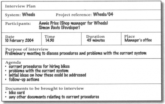
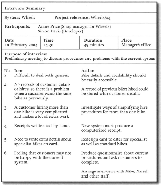
In order to gather as much relevant information as possible, the interview must be well prepared. It is useful to produce a plan that is given to the interviewee in advance, stating the time and place of the interview, the kind of topics that will be covered and any documents that the interviewee should bring along. The following figure shows the plan for an interview with Annie Price, the shop manager at Wheels. The interviewer is Simon Davis, a system developer on the Wheels project.
Extract from the interview:
- SD: ...so could you tell me what happens typically when someone wants to hire a bike? Just talk me through it bit by bit.
- Annie: OK, well say someone comes in and says they want to hire a bike for that afternoon, so I ask them if they know what sort they want- it's always easier in that case. Then, when I've got an idea of what they're looking for, I get Naresh or one of the other mechanics to come and suggest a couple of bikes that might suit.
- SD: And is the customer always happy with that?
- Annie: Yes, usually they go with whatever Naresh says. He's the head mechanic and he's pretty clued up about bikes. We hardly ever get any of them coming back and complaining after the ride.
- SD: Ok, and what order do you keep them in?
- Annie: We keep them in the order of the bike numbers - it's the only way really- though it does cause problems with queries. For example, the other day I had a man on the phone wanting to know if we had two bikes, a Raleigh Pioneer for him and a Dawes Galaxy for his partner, and how much it would cost for three day's hire. First of all I had to look on the shop floor to see if we'd got the right bikes, then I had to search through all the cards and then I had to work out how much it was going to cost him. He was very patient, but that sort of thing takes ages. Anyway, I'll show you one of the cards.
- SD: Thanks. Can you tell me - are the hire charge and the deposit the same for all the bikes?
- Annie: No, they vary a lot. Well, you couldn't charge the same for a child's bike as for an 18-gear racer, could you? Anyway, then I fill in all the details on the bike card, the customer gives me the money to cover the hire and deposit and off they go.
- SD: Don't they get a receipt?
- Annie: Oh yes, sorry, I forgot. I write one out from the receipt book. It would be nice if we could use the computer system for that, but all we've actually got on it is a list of the bikes that we own and all their details like make, model, size, cost and all that. Even that can be a bit of a problem -for Naresh that is- he's the one who has to enter all the details about the bikes that the boss buys in and that can be really tedious.
- SD: Well, I'm sure we can improve on that. So tell me, if a customer hires more than one bike, how do you record that?
- Annie: Well, you can see this card only has details for this particular bike, so if a customer is hiring three bikes I have to put the details on three separate cards, including writing out their name and address three times. We have to do it like that because sometimes people hire more than one bike, but for different times. For example, we get families on holiday who hire bikes for the children for the whole week, but maybe just a couple of days for the parents. When people do want a number of bikes it's a bit of a pain looking out all the cards and filling in the same customer details on each one, not to mention working out what it all costs. We once had a customer who hired 20 bikes for his daughter's birthday party, which took me ages. That was a bit of a one-off though; we do get requests for parties and events, but it's generally the special stuff that they want.
- SD: Special stuff?.
- Annie: Sorry, I should have told you about that. We have some novelty items that Mike (he's the boss) has picked up at auctions, like a couple of genuine working penny farthing cycles. Those are very popular for period style photos and charity events. People tend to notice them, so they're a really good advertisement for us as well. Last year we had a local couple who hired one of our old tandems for their wedding and we got loads of publicity from that.
- SD: Presumably hiring those out is rather more complicated
- Annie: Oh yes, we have to write on the card extra details about our special bikes, such as their age, value and restrictions on what they can be hired for.
- SD: OK, so just to get back to the actual hire procedures. You fill in the details on the card, the customer pays and you give them a receipt.
- Annie: Yes that's it really.
- SD: Thanks, that's very helpful. So what happens when the customer comes back with the bike?
- Annie: Well they come in, usually all hot and sweaty, but never mind that. I get the bike number and I check that the bike they're returning is the one on the card. And I have to check the return date as well, because if they're late they have to pay extra.
- SD: And you return the customer's deposit if they bring back the bike on time?
- Annie: Usually, but not if the bike's been damaged of course. One of the mechanics gives every bike a quick check to make sure it's in reasonable condition. If there's a problem we keep some of the deposit and if it's really bad then we keep all of it. We once had one that was a write-off; goodness knows what the customer had been doing with it. The bikes are insured of course, but keeping deposits helps keep down the claims.
- SD: Can you tell me about your customers in general, do you think they're happy with the hire system as it is, or do you get a lot of complaints?
- Annie: I don't think it's too bad, though we do get complaints occasionally. I don't think the system's very efficient; for example, it can be really slow if I'm trying to work out the cost of hiring more than one bike. If it's my day off and one of the others is in charge it's even slower because they're not used to it. Sometimes I think the customers are just too nice to complain. They can see that I'm doing my best and they don't want to get me into trouble. I think if you asked them they might say that there are quite a few things that could be improved.
- SD: Well I'm thinking of doing just that. Would it be all right to leave a short questionnaire on the counter for customers to fill in and return to you? I think it would give us a good idea of how your customers view the hire system and where they think the problems are.
- Annie: That's a great idea. You can leave them on the counter and I'll make sure that every customer gets one...
From what Annie says, we can identify a number of areas that seem to be causing problems:
- It takes a long time to deal with queries such as 'Have you got 5 women's mountain bikes?' or 'How much would it cost to hire two adult racers for three days?'
- The only way Annie can tell if a bike is in the shop and available for hire is by looking on the shop floor.
- The bike cards are kept in number order, so Annie has to know the bike number before she can find its card.
- Wheels does not seem to keep any records of their customers' details or the bikes that they hired on previous occasions.
- When a customer hires more than one bike, Annie has to fill out a separate card for each one.
- Annie has to write out receipts for the customers by hand.
- Bike return is slow because it takes Annie a while to calculate whether the whole deposit can be returned.
- Important information about novelty bikes has to be written on the standard bike card.
Questionnaires
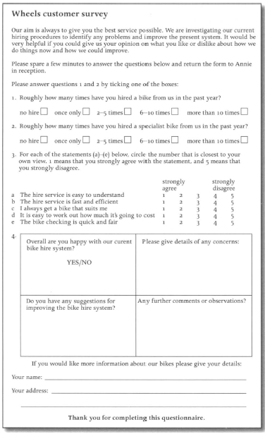
It is unlikely that the developer will be able to interview customers, and in any case, he is only looking for a small amount of information from each person, so the most effective method of elicitation is to use a questionnaire:
Scenarios
Scenarios have been popular as a method of requirements elicitation for many years and have now become closely associated with object-oriented development of systems. A scenario is a sequence of interactions between a user and the system carried out in order to satisfy a specified goal.
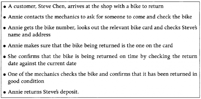
Scenario for the return of a bike:
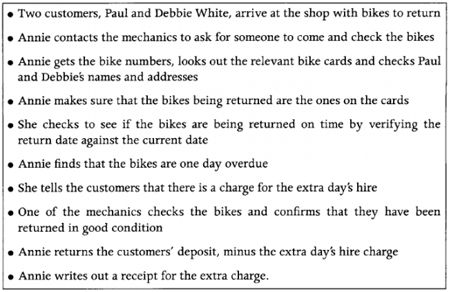
As we can see from the example in Figure 2. 4, a scenario is a sequence of particular events, not a general description. This example illustrates the straightforward return of a bike, without any problems. However, this is only one possible scenario for a bike return, and it is the developer's job to find out what happens in all possible cases. The following figure shows another scenario for bike return, which is slightly more complicated.
A more complicated scenario for the return of a bike in the current Wheels system:
It is also important for the developer to find out about what happens when a goal is not achieved, for example a customer may come into Wheels to return a bike, but the bike card is missing. A scenario should be written for this sort of situation in the same way as for normal cases, so that the developer knows how the system should respond when things are not straightforward.
A further advantage of using scenarios in object-oriented development is that they can later be translated into interaction diagrams, which are part of the toolbox of object-oriented techniques.
Requirements specification
The main purpose of requirements specification is to collate, order and record the mass of information gathered during the elicitation stage. The problems and requirements list that is produced from this stage is a crucial deliverable in the development process.
In this chapter we illustrate two ways of recording requirements in the early stages of development.:
- The Problem definition
- The problems and requirements list
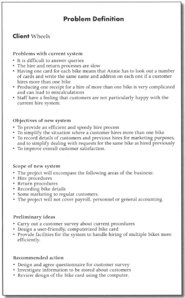
The Problem definition
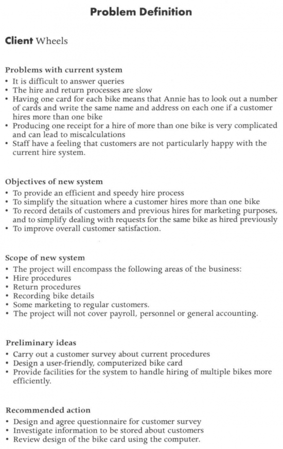
It's a brief initial summary of what has been discovered during the requirements elicitation process. An example of an initial problem definition for the Wheels system is shown in the following figure:
The problems and requirements list
The second, more detailed approach to recording requirements at this stage is the problems and requirements list. Requirements are recorded more formally and more comprehensively, so that the clients and users can check that the developer has a good understanding of what is wanted. Each requirement should be given a unique number or code, so that it can be clearly identified right through the development process. There should be a brief description of the requirement, including where it came from and the date it was identified. It is impossible for a developer to satisfy all the wishes of clients and users, so requirements should be prioritized by designating each one as essential, desirable or optional. It is also helpful to document any related requirements and any documents that are associated with this requirement. Finally, if there are changes to a requirement during development, these should also be documented, including the reason for the changes and the effect this may have on the system. The following figure shows two examples of early requirements specifications from the Wheels system.
Requirements validation
The purpose of the validation stage of requirements engineering is to make sure that the developer has understood and recorded correctly the wishes and needs of the clients and users of the new system.
A written summary of each interview should be prepared by the developer and given to the interviewee shortly after the interview. This gives the interviewee an opportunity to check for any gaps or errors in the information that the developer has recorded from the interview. The summary should cover the main points raised during the discussion and any future action to be taken. A summary of the interview with Annie Price, the Wheels' shop manager, can be seen in the following Figure:
One of the most effective methods of validation is to crossreference information obtained from different elicitation approaches. For example, scenarios produced in conversations with users may be compared with notes from observations of the same users carrying out day-to-day tasks.
List of requirements for the Wheels system
The list below is a brief summary of the requirements for the Wheels system that have been gathered during the requirements elicitation process. Problems with the current system have already been covered in the interview with Annie and the section following the interview, but the implications for the new system have not yet been explicitly identified. This list will serve as a basis for the object-oriented development of Wheels that is the subject of the rest of the book.
The new Wheels system must:
- R1: keep a complete list of all bikes and their details including bike number, type, size, make, model, daily charge rate, deposit (this is already on the Wheels system)
- R2: keep a record of all customers and their past hire transactions
- R3: work out automatically how much it will cost to hire a given bike for a given number of days
- R4: record the details of a hire transaction including the start date, estimated duration, customer and bike, in such a way that it is easy to find the relevant transaction details when a bike is returned
- R5: keep track of how many bikes a customer is hiring so that the customer gets one unified receipt not a separate one for each bike
- R6: cope with a customer who hires more than one bike, each for different amounts of time
- R7: work out automatically, on the return of a bike, how long it was hired for, how many days were originally paid for, how much extra is due
- R8: record the total amount due and how much has been paid
- R9: print a receipt for each customer
- R10: keep track of the state of each bike, e.g. whether it is in stock, hired out or being repaired
- R11: provide the means to record extra details about specialist bikes.
UML
The UML (Unified Modeling Language) is an international industry standard graphical notation for describing software analysis and designs.
The Unified Mode]ling Language, or UML, is a set of diagrammatic techniques, which are specifically tailored for object-oriented development, and which have become an industry standard for modelling object-oriented systems. The UML grew out of the work of James Rumbaugh, Orady Booch and Ivor Jacobson, and has been approved as a development standard by the Object Management Group. Before discussing the UML in detail we should explain briefly what we mean by 'mode]ling' in this context, and why it is an important part of software system development.
Modelling:
Architects and engineers have always used special types of drawing to help them to describe what they are designing and building. In the same way, software developers use specialized diagrams to model the system that they are working on throughout the development process. Each model produced represents part of the system or some aspect of it, such as the structure of the stored data, or the way that operations are carried out. Each model provides a view of the system, but not the whole picture.
Fundamental UML models:
As we mentioned in the previous section, the UML is not a development method since it does not prescribe what developers should do, it is a diagrammatic language or notation, providing a set of diagramming techniques that model the system from different points of view. The following table shows the principal UML models with a brief description of what each can tell us about the developing system.
The 4 + 1 view: The authors of UML, Booch et al., (1999), suggest we look at the architecture of a system from five different perspectives or views:
- The use case view
- The design view
- The process view
- The implementation view
- The deployment view.
This is known as the 4 + 1 view (rather than the 5 views) because of the special role played by the use case view. The use case view of the system is the users' view: it specifies what the user wants the system to do; the other 4 views describe how to achieve this.
There are five fundamental UML models:
- Use case model
- Class model,
- Sequence model
- State model
- Activity diagrams
Use case model
Use cases model the user's view of the functionality of a system. What it does that is of value to the user. Use cases are normally presented in a graphical form, the use case diagram, supported by textual descriptions, use case and actor descriptions, and scenarios.
The use case model consists of:
- A use case diagram,
- A set of use case descriptions,
- A set of actor descriptions, and
- A set of scenarios.
A use case diagram
The use case diagram models the problem domain graphically using four concepts:
- The use case,
- The actor: specifies a role played by a user or any other system that interacts with the subject.
- The relationship link, and
- The boundary.
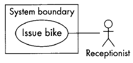
UML symbols used to model these concepts:
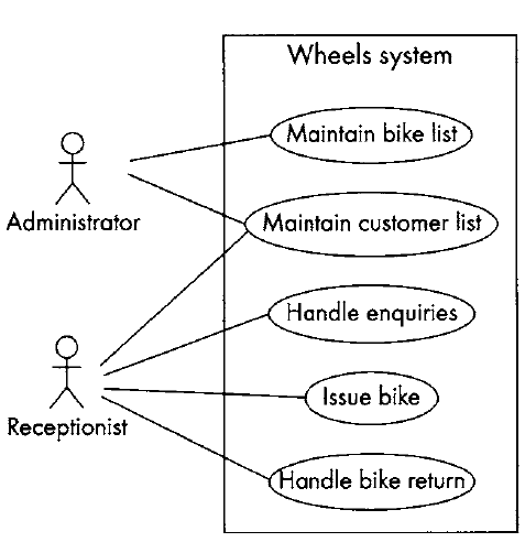
- A use case: an ellipse labelled with the name of the use case. Conventionally we start each use case name with a verb to make the point that use cases represent processes. So we have 'Maintain customer list' rather than 'Customer list', 'Handle enquiries' rather than 'Enquiries'.
- An actor: a stick figure labelled with the name of the actor. We capitalize actor names so that they are easy to identify as such (e.g. Administrator, Receptionist). The stick figure icon is used even when the actor is non-human, e.g. another computer system or an organization.
- A use case relationship: a line linking an actor to a use case. The line shows us which actors are associated with which use cases. This relationship is also known as a communication association.
- The boundary: a line drawn round the use cases to separate them from the actors and to delineate the area of interest. Can be labelled to indicate the diagram domain. The boundary is often omitted.
The use cas:
The functionality of the system is initially represented through use cases, which describe the main activities of the system from the perspective of the user.
What we do when identifying use cases is to divide up the system's functionality into chunks, into the main system activities. What dictates the split is what the user sees as the separate jobs or processes (the tasks he will do using the system).
Identifying use cases from the actors:There are several ways of approaching use case identification. One is to identify the actors, the users of the system, and for each one, to establish how they use the system, what they use it to achieve.
If we look at the interview in Chapter 2 we can see that Annie and Simon start off by talking about issuing bikes, one of the main jobs that make up Annie's working day. Issuing bikes therefore will be one of the use cases. Issuing bikes involves: finding a suitable bike, calculating the hire charge, collecting the money, issuing a receipt and recording details of the customer and the hire transaction.
The interview moves on to discuss dealing with the return of a bike. Annie sees this as a separate job from issuing the bike, it is separated in time and involves a different set of procedures- checking the date and the condition of the bike and returning the deposit.
Annie tells us in the interview that a list of bikes is already held on the computer, but they do not seem to be able to use it to help them in their work. The bike list needs to be stored so that it can be used to answer queries about what bikes Wheels have, whether they are available or on hire, what their deposit and hire charges are and so on. Maintaining this bike list is another use case.
Handling queries is seen by Annie as a separate job from issuing bikes. She often gets people coming into the shop or phoning just to check on the range of bikes available and get an idea of costs. This sometimes leads to a hire, but more often it does not. We can therefore identify Handle enquiries as a separate use case.
It also emerges from the interview that no record is kept of customer details or of what bikes they have hired on previous occasions. This sort of information would be useful for marketing purposes and to simplify dealing with requests for the same bike (see the Problem Definition (Figure 2.6), the Problems and Requirements List (Figure 2.7) and the Interview Summary (Figure 2.8)). Maintain customer list can therefore be identified as a use case.
Identifying use cases from scenarios:Another approach to identifying use cases is to start with the scenarios. We have already mentioned scenarios in Chapter 2 - a scenario describes a series of interactions between the user and the system in order to achieve a specified goal. A scenario describes a specific sequence of events, for example what happened when Annie successfully issued a bike to a customer.
Each use case represents a group of scenarios. Scenarios belonging to the same use case have a common goal- each scenario in the group describes a different sequence of events involved in achieving (or failing to achieve) the use case goal. A continuación, we describe scenarios belonging to the 'Issue bike' use case; in both cases Annie is trying to issue a bike to a customer.
Successful scenario for the use case Issue bike:
- Stephanie arrives at the shop at 9.ooam one Saturday and chooses a mountain bike
- Annie sees that its number is 468
- Annie enters this number into the system
- The system confirms that this is a woman's mountain bike and displays the daily rate (s and the deposit (s
- Stephanie says she wants to hire the bike for a week
- Annie enters this and the system displays the total cost s + s = s
- Stephanie agrees this
- Annie enters Stephanie's name, address and telephone number into the system
- Stephanie pays the s
- Annie records this on the system and the system prints out a receipt
- Stephanie agrees to bring the bike back by 9.ooam on the following Saturday.
Scenario for "Issue bike" where the use case goal is not achieved:
- Michael arrives at the shop at 12.oo on Friday
- He selects a man's racer
- Annie see the number is 658
- She enters this number into the system
- The system confirms that it is a man's racer and displays the daily rate (€2) and the deposit (€55)
- Michael says this is too much and leaves the shop without hiring the bike.
En la siguiente figura we shows a use case diagram of the Wheels case study. The functionality of the new system has been divided into five use cases: 'Maintain bike list', 'Maintain customer list', 'Handle enquiries', 'Issue bike' and 'Handle bike return'. Conceptually a use case diagram is similar to a top-level menu which lists the five main things that the system does. Each use case is linked by a line to an actor. The actor, represented by a stick figure, is the person (sometimes a computer system or an organization) who uses the system in the way specified in the use case or who benefits from the use case.
Use case descriptions
The use case description is a narrative document that describes, in general terms, the required functionality of the use case.
The class diagram
The class diagram is central to object-oriented analysis and design, it defines both the software architecture, i.e. the overall structure of the system, and the structure of every object in the system. We use it to model classes and the relationships between classes, and also to model higher-level structures comprising collections of classes grouped into packages. The class diagram appears through successive iterations at every stage in the development process. It is used first to model things in the application domain as part of requirements capture. Subsequently, with classes added which are part of the solution not the problem domain (e.g. interface classes), it is used to design a solution. Finally, with classes added to facilitate the implementation (e.g. buttons, windows, mouselisteners, etc.), it is used to design the program code.
Stages in building a class diagram
One way to approach the class diagram is by use case realization. In use case realization we look at each use case in turn and decide what classes we would need to provide the functionality modelled in the use case. The group of classes required by a use case is called a collaboration. When each use case has been analysed, the resulting collaborations are amalgamated into a unified class diagram. We will look at collaborations in Chapter 6, but for the moment we are going to use a different approach to developing the class diagram. We will develop a domain model, i.e. a class diagram that sets out to model all of the classes in the problem domain in one go, not use case by use case. Both approaches should eventually arrive at the same model.
Stages to build a class diagram (domain model):
- Identify the objects and derive classes
- Identify attributes
- Identify relationships between the classes
- Write a data dictionary to support the class diagram
- Identify class responsibilities using CRC cards
- Separate responsibilities into operations and attributes
- Write process specifications to describe the operations.
Identify the objects and derive classes:
Class diagrams are a very useful way of modelling the structure of the objects in a system and the links between them. However, when we are trying to design a new software application, we don't know what the classes are in advance and we will often start by looking for objects before making decisions about what their class will be.
Objects come in different categories; being aware of the categories gives us an idea of the sorts of things to look for. Objects at the analysis stage will be things that have meaning in the application domain. They can be:
- People (such as customers, employees, students, librarians)
- Organizations (such as companies, universities, libraries)
- Physical things (such as books, bikes, products)
- Conceptual things (such as book loans and returns, customer orders, seating plans).
Various techniques can be used for object identification, none of them are foolproof, none can be guaranteed to produce a definitive list of objects and classes; they are just guidelines that might help. A good starting point is to look at the documentation about the system produced so far and to search for nouns in any description of the system requirements, preferably one that is complete and concise.
Object identification using noun analysis:
- First, find a complete but concise description of the system requirements. The Problem Definition in Figure Figure 1 (Chapter 2 del libro) is often a good place to look. Use case descriptions are also useful for this purpose, although for a complete description of the system you would have to look at all of the use case descriptions.
- Pick out all of the nouns and noun phrases and underline them. This usually provides a rather long list of possible (or candidate) objects, many of which are obviously unsuitable and some of which are unsuitable in more subtle ways.
- Reject unsuitable candidates by applying a list of rejection criteria.
For our object analysis we will use the list of requirements produced at the end of Chapter 2:
- R1: keep a complete list of all bikes and their details including bike number e typer sizer maker modelr daily charge rate, deposit; (this is already on the Wheels system)
- R2: keep a record of all customers and their past hire transactions;
- R3: work out automatically how much it will cost to hire a given bike for a given number of days
- R4: record the details of a hire transaction including the start date, estimated duration, customer and bike, in such a way that it is easy to find the relevant transaction details when a bike is returned
- R5: keep track of how many bikes a customer is hiring so that the customer gets one unified receipt not a separate one for each bike
- R6: cope with a customer who hires more than one bike, each for different amounts of time
- R7: work out automatically, on the return of a bike, how long it was hired for, how many days were originally paid for, how much extra is due
- R8: record the total amount due and how much has been paid
- R9: print a receipt for each customer
- R10: keep track of the state of each bike, e.g. whether it is in stock, hired out or being repaired
- R11: provide the means to record extra details about specialist bikes.
The candidate objects that result from this exercise are:
- list of bikes
- details of bikes" bike number, type, size, make, model, daily charge rate, deposit
- Wheels system
- record of customers
- past hire transactions
- bike
- number of days
- details of a hire transaction: start date, estimated duration
- customer
- receipt
- different amounts of time
- return of a bike
- total amount due
- state of each bike
- extra details about specialist bikes.
We now examine the list of candidate objects and reject those that are unsuitable. Objects should be rejected if they are:
- Attributes: Sometimes it is clear that a noun is an attribute of an object rather than an object itself. Bike number, type, size, make, model, daily charge rate and deposit are clearly attributes of a bike object rather than objects in their own right. Similarly, hire transaction sounds like a possible object, with start date and estimated duration as its attributes. Number of days also sounds like an attribute as do different amounts of time, total amount due and extra details about specialist bikes. Specialist bike, however, sounds like an object. If in doubt ask yourself whether the noun you are considering would be likely to have attributes of its own. Would it have behaviour?
- Redundant: Sometimes the same concept appears in the text in different guises. Here past hire transactions and hire transaction are probably the same thing. Different amounts of time, number of days and estimated duration are probably the same thing - all three refer to the length of a hire (in any case they are attributes, not objects).
- Too vague: If we don't know exactly what is meant by a term it is unlikely to make a good class. For this reason we reject return of a bike as an object. Return of bike is really an event and features in our use case model. Any data we might need to store about bike returns (e.g. date of return) can probably be bundled with the data about hires.
- Too tied up with physical inputs and outputs: This refers to something that exists in the real world but is a product of the system or data input to the system and not an object in its own right. For example, a bill exists in the real world, but is something the system outputs from data it already stores and as such would not be modelled as a class. Receipt qualifies for rejection under this heading. Receipt is an output; it is also redundant as we either store or can calculate the details we would print on it. List of bikes also requires some consideration. If we have an object to represent each bike, we can use these objects to produce a list. Bike, therefore, is a good candidate object, but we can drop the list at this stage. The same applies to record of customers and customer.
- Associations: In the class diagram in Figure 5.1 hires is modelled as an association between Customer and Bike. Whether hires is an object or an association raises some interesting issues and we will postpone that decision until later. The general rule in this situation is that if there is data associated with the relationship (and in this case there is), then we probably want to model it as an object.
- Outside the scope of the system: In this category would be anything we have decided to be beyond the system boundary. For example, according to the Problem Definition in Chapter 2 the system will not cover payroll, personnel or general accounting.
- Really an operation or event: This criterion is quite confusing and should be treated with care. If a candidate object seems to have no data associated with it, then it might be better modelled as an operation on another class. Quite often, however, operations and events are modelled as objects. For example, hiring a bike might be described as an event but as there is associated data, start date and number of days, we are more likely to want to model it as an object (see below).
- Represent the whole system: It is not normally a good idea to have an object that represents the whole system; we want to divide the system into separate objects. Wheels system should be rejected for this reason.
That leaves us with the candidate objects:
- bike
- customer
- hire transaction
- specialist bikes
We can use these objects to form the basis of our class diagram (remember that class names are always singular):
CRC cards
CRC (class-responsibility-collaboration) cards are not officially part of the UML, but are regarded as a valuable technique that works extremely well with it.
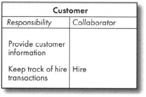
The aim of the CRC card technique is to divide the overall functionality of the system into responsibilities which are then allocated to the most appropriate classes.Once we know the responsibilities of a class, we can see whether it can fulfil them on its own, or whether it will need to collaborate with other classes to do this.
On the front of the card is a high-level description of the class, and the back of the card records the class name, responsibilities and collaborations (if any). An example of a CRC card for the Customer class in the Wheels system is shown in the following Figure. We can see from the figure that the Customer class has two responsibilities; it is able to carry out the first of these (Provide customer information) on its own, but in order to carry out the second responsibility (Keep track of hire transactions) it will have to collaborate with the Hire class.
Software developers find that the simplicity of CRC cards, their lack of detail, make them an ideal tool for exploring alternative ways of dividing responsibilities between classes. It's easy to scrap one design and start again without agonizing about the amount of work that is being discarded. Another way of exploring alternatives is to use sequence diagrams, which are discussed later in this chapter. In practice, however, sequence diagrams show too much detail and are too slow to draw to be useful for this purpose. They are much more useful for documenting the detail of design decisions once these have been reached using CRCs.
This size of card (1ocm x 15cm) is used rather than a sheet of A4 paper to encourage system developers to restrict the size of each class in terms of the number of its responsibilities. Good object-oriented design depends on having small cohesive classes, each of which has limited, but well-defined functionality. The CRC card also encourages developers to specify responsibilities at a high level rather than write lots of low-level operations. The general rule is that no class should have more than three or four responsibilities.
Interaction diagrams
We have already mentioned in Chapter 4 that objects collaborate to achieve the functionality required of them by sending messages. Interaction diagrams model the messaging between a collaboration of objects that will take place in the execution of a specific scenario.
By the time we come to do the interaction diagrams we have already done a lot of analysis: we know what the system has to do, we know about the classes and attributes, and we have had our first real ideas about the nature of the relationships between classesthey have to be able to support the collaborations between objects that we specified in the CRC analysis.
Sequence diagrams
When students who are new to object-oriented technology, especially those who have been trained in procedural methods, first meet object-oriented code, they are staggered by the way the flow of control jumps about on the page. In procedural programming, the sequence of execution proceeds in an orderly fashion from the top of a page of code to the bottom, with only the odd jump off to a procedure. Quite the opposite happens in the execution of an objectoriented program; the sequence of control jumps from object to object in an apparently random manner. This is because, while the code is structured into classes, the sequence of events is dictated by the use case scenarios. Even for those experienced in object technology, it is very hard to follow the overall flow of control in object-oriented code. Programmers, maintainers and developers need a route map to guide them; this is provided by the sequence diagram.
Sequence diagrams show clearly and simply the flow of control between objects required to execute a scenario. A scenario outlines the sequence of steps in one instance of a use case from the user's side of the computer screen, a sequence diagram shows how these steps translate into messaging between objects on the computer's side of the screen.
Collaboration diagrams
State diagrams
Activity diagrams

