Difference between revisions of "Networking"
Adelo Vieira (talk | contribs) (→IP addressing) |
Adelo Vieira (talk | contribs) (→Subnet mask) |
||
| (2 intermediate revisions by the same user not shown) | |||
| Line 335: | Line 335: | ||
*Si tenemos: 172.17.0.1/24, podemos fácilmente saber que: ( Ver http://jodies.de/ipcalc ) | *Si tenemos: 172.17.0.1/24, podemos fácilmente saber que: ( Ver http://jodies.de/ipcalc ) | ||
| − | <syntaxhighlight lang=""> | + | <syntaxhighlight lang="shell"> |
Address: 172.17.0.1 10101100.00010001.00000000 .00000001 | Address: 172.17.0.1 10101100.00010001.00000000 .00000001 | ||
Netmask: 255.255.255.0 = 24 11111111.11111111.11111111 .00000000 | Netmask: 255.255.255.0 = 24 11111111.11111111.11111111 .00000000 | ||
| Line 349: | Line 349: | ||
*Ahora, en el caso de 172.17.0.1/27, las cosas no son tan evidentes: | *Ahora, en el caso de 172.17.0.1/27, las cosas no son tan evidentes: | ||
| − | <syntaxhighlight lang=""> | + | <syntaxhighlight lang="shell"> |
Address: 172.17.0.1 10101100.00010001.00000000.000 00001 | Address: 172.17.0.1 10101100.00010001.00000000.000 00001 | ||
Netmask: 255.255.255.224 = 27 11111111.11111111.11111111.111 00000 | Netmask: 255.255.255.224 = 27 11111111.11111111.11111111.111 00000 | ||
| Line 363: | Line 363: | ||
*172.17.0.1/30 | *172.17.0.1/30 | ||
| − | <syntaxhighlight lang=""> | + | <syntaxhighlight lang="shell"> |
Address: 172.17.0.1 10101100.00010001.00000000.000000 01 | Address: 172.17.0.1 10101100.00010001.00000000.000000 01 | ||
Netmask: 255.255.255.252 = 30 11111111.11111111.11111111.111111 00 | Netmask: 255.255.255.252 = 30 11111111.11111111.11111111.111111 00 | ||
| Line 388: | Line 388: | ||
<br /> | <br /> | ||
| + | ====Calculating the number of hosts based on the subnet mask==== | ||
| + | For example, for a subnet mask of 20: | ||
| + | 2**(32-20) - 2 = 4094 | ||
| + | -2 is becuse the first one is the network address and the last one the broadcast address. | ||
| + | |||
| + | |||
| + | <br /> | ||
| + | |||
===Network address=== | ===Network address=== | ||
| Line 1,139: | Line 1,147: | ||
<br /> | <br /> | ||
| − | == | + | ==[[Network Simulation using PacketTracer]]== |
| + | |||
| + | |||
| + | <br /> | ||
Latest revision as of 11:44, 7 September 2024
Contents
- 1 Resumen para el examen de Network Service Management and Virtualisation
- 2 Wireless and WAN connectivity CA
- 3 Sistema binario
- 4 Terminología
- 5 TCP/IP
- 6 Introduction to Internetworking and Network equipments
- 7 IP addressing
- 8 WAN (Wide Area Network)
- 9 Routing
- 10 Ethernet
- 11 Wireless networks
- 12 Para ver las características de las tarjetas de red (network card)
- 13 DHCP
- 14 DNS
- 15 Using Wireshark to observe traffic
- 16 Campus LAN and Wireless LAN Design Guide - Cisco
- 17 Network Simulation using PacketTracer
Resumen para el examen de Network Service Management and Virtualisation
Media:Resumen para el examen networking.pdf
- DHCP
- DNS
- ARP
- TCP
- HTTP
Some important questions that you should know:
- A network manager asks you to write down the steps for a DNS query when you open your browser and type www.google.com
- The network manager then asks you to describe the difference between a recursive and iterative query
- What typical transport layer protocol and port does DNS use for DNS lookups
Wireless and WAN connectivity CA
Sistema binario
Conversión de un número en el sistema decimal al binario:
Conversión de Binario a decimal:
Terminología
Protocols
Think of protocols as a standard way of communication between a client and a server.
LAN
A Local Area Network is a computer network that interconnects computers within a limited area such as a residence, school, laboratory, university campus or office building. https://en.wikipedia.org/wiki/Local_area_network
WAN
A Wide Area Network is a telecommunications network or computer network that extends over a large geographical distance. https://en.wikipedia.org/wiki/Wide_area_network
Puertos
- The wireless router’s WAN (Internet) port (el puerto WAN (Internet) del wireless router).
- The wireless router’s LAN (Ethernet) ports.
- RS-232: is a standard for serial communication transmission of data. https://en.wikipedia.org/wiki/RS-232
Elegir el puerto correcto
- Cuando se conecta un cable a una PC en Packet Tracer, el programa propone (por defecto) conectarlo al puerto FastEthernet, USB o RS-232. Hasta ahora hemos estado usando el puerto FastEthernet.
- Cuando se conecta un cable a un Router, PacketTracer propone el puerto Internet o Ethernet. Creo que el puerto Internet se usa cuando estamos conectando el Router con una WAN y el Ethernet es para una LAN.
Cables
- As a rule, between different divices we use a straight cable an between same divices a cross-over cable (Creo que el Prof. confirmó esto, no estoy seguro)
- Crossover cable:
- From a PC to the wireless router’s WAN (Internet) port.
- Straight through cable:
- From PC to one of the wireless router’s LAN (Ethernet) ports.
TCP/IP
https://en.wikipedia.org/wiki/Internet_protocol_suite
The Internet protocol suite is the conceptual model and set of communications protocols used on the Internet and similar computer networks.
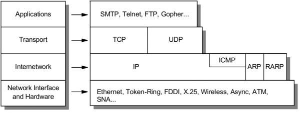
The Internet protocol suite provides end-to-end data communication specifying how data should be packetized, addressed, transmitted, routed, and received. This functionality is organized into four abstraction layers which classify all related protocols according to the scope of networking involved. From highest to lowest, the layers are:
- The application layer: it provides process-to-process data exchange for applications. HTTP, FTP, DNS etc.
- The transport layer: handling host-to-host communication. TCP, UDP, etc.
- The internet (Internetwork) layer: providing internetworking between independent networks. IP (IPv4, IPv6), etc.
- Network interface and Hardware [Datalink, Physical] layer: containing communication methods for data that remains within a single network segment (link). Ethernet, Wireless, etc.
Applications
HTTP
The HTTP request. HTTP is the pull protocole. A client pulls a page from the server.
FTP
DNS
Transport
TCP
TCP (Transmision Control Protocol)
Internetwork
IP
Network interface and Hardware [Datalink, Physical]
Ethernet
Wireless
OSI model
https://en.wikipedia.org/wiki/OSI_model#Comparison_with_TCP.2FIP_model
| OSI Model | ||||
|---|---|---|---|---|
| Layer | Protocol data unit (PDU) | Function | ||
| Host layers |
7. Application | Data | High-level APIs, including resource sharing, remote file access | |
| 6. Presentation | Translation of data between a networking service and an application; including character encoding, data compression and encryption/decryption | |||
| 5. Session | Managing communication sessions, i.e. continuous exchange of information in the form of multiple back-and-forth transmissions between two nodes | |||
| 4. Transport | Segment (TCP) / Datagram (UDP) | Reliable transmission of data segments between points on a network, including segmentation, acknowledgement and multiplexing | ||
| Media layers |
3. Network | Packet | Structuring and managing a multi-node network, including addressing, routing and traffic control | |
| 2. Data link | Frame | Reliable transmission of data frames between two nodes connected by a physical layer | ||
| 1. Physical | Bit | Transmission and reception of raw bit streams over a physical medium | ||
Introduction to Internetworking and Network equipments
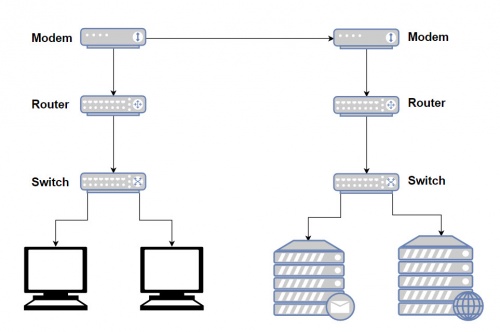
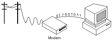
Modem
https://www.webopedia.com/TERM/M/modem.html
http://homepages.uc.edu/~thomam/Net1/Modems%20&%20D-A%20Conversion/modem_main.html
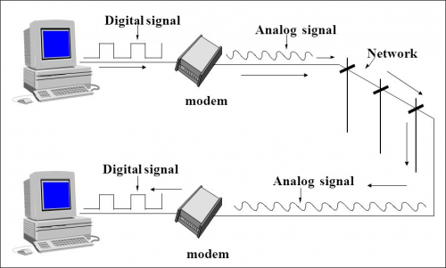
A modem (Short for modulator-demodulator) is a device or program that convert digital information to analog signals (modulation), and to convert analog signals back into useful digital information (demodulation). It enables a computer to transmit data over, for example, telephone or cable lines. http://homepages.uc.edu/~thomam/Net1/Modems%20&%20D-A%20Conversion/modem_main.html
Computer information is stored digitally, whereas information transmitted over telephone lines is transmitted in the form of analog signal. A modem converts between these two forms.
Router
http://www.diffen.com/difference/Router_vs_Switch
Router and switches are both computer networking devices that allow one or more computers to be connected to other computers, networked devices, or to other networks.
The functions of a routers, switch and hub are all different, even if at times they are integrated into a single device.
Routers can connect wired or wireless (WiFi) networks. A switch is used for wired networking connections.
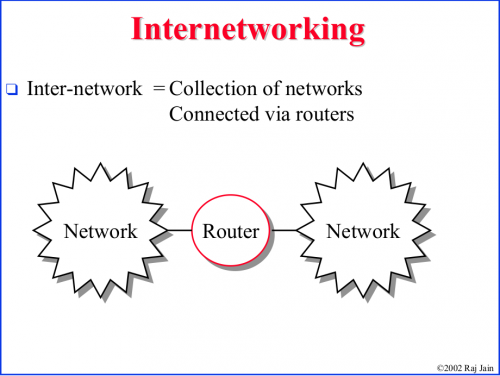
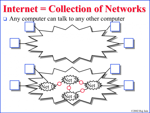
A router is a networking device that connects computer networks (connect two or more logical subnets). For example, connecting a home network with the Internet.
Routers operate at Layer 3 (network layer) of the OSI model. They direct traffic and perform other functions to efficient network operation. For example, they receive TCP/IP packets, look inside each packet to identify the source and target IP addresses, then forward these packets as needed to ensure the data reaches its final destination.
In addition, routers often perform network address translation (NAT), which allows all devices on a subnetwork (e.g., all devices in a home) to share the same public IP address.
Como se mencionó arriba, routers can connect wired or wireless (WiFi) networks.
Existen diferentes tipos de Routers. El uso y la manera de configurarlos varía notablemente:
The largest routers (such as the Cisco CRS-1 or Juniper PTX) interconnect the various ISPs, or may be used in large enterprise networks. Smaller routers usually provide connectivity for typical home and office networks. https://en.wikipedia.org/wiki/Router_(computing)
Al parecer se habla también Wireless Routers. Creo sin embargo que este dispositivo sería un Router equipado con un AP y una tarjeta de red wireless.
En el Lab 1 se realiza un modelado de networks en el cual se emplea un Wireless Router. Este Wireless Router podría, por ejemplo, representar el Router que se encuentra integrado en la Box de nuestra home network. En el Lab 1, note que en este Router las configuraciones se ralizan a través de un GUI.
En el Lab 4: Configuring basic router settings with the Cisco IOS CLI, se presenta un modelado de network en el cual se emplea un Router Cisco. Note que este tipo de Routers son configuring with the Cisco IOS CLI (línea de comandos).
Switch
A network switch is a computer networking device that is used to connect many devices together on a single computer network (within one local area network (LAN)).
Switches are incapable of joining multiple networks or sharing an Internet connection.
A switch is also called switching hub, bridging hub, or MAC bridge. Switches use MAC addresses to forward data to the correct destination. A switch is considered a Layer 2 device, operating at the data link layer; switches use packet switching to receive, process and forward data.
A switch is considered more advanced than a hub because a switch will on send msg to device that needs or request it
Access point
The Access Point (AP) is the central node in 802.11 wireless implementations. It is the interface between wired and wireless network
An access point is a hardware device that receives data by wired Ethernet and, using 2.4GHz or 5GHz radio waves bands, converts to a wireless signal. It sends and receives wireless traffic to and from nearby wireless clients.
For a home environment, most often you have a router, a switch, and an AP «embedded in one box (into a single device)», making it really usable for this purpose.
IP addressing
IP address
Dirección IP
Classful network
Clases de public IP addresses: https://www.cloudaccess.net/cloud-control-panel-ccp/157-dns-management/322-subnet-masks-reference-table.html
| Classe | Bits de départ | Début | Fin | Notation CIDR | Masque de sous-réseau par défaut |
|---|---|---|---|---|---|
| Classe A | 0 | 0.0.0.0 | 127.255.255.255 | /8 | 255.0.0.0 |
| Classe B | 10 | 128.0.0.0 | 191.255.255.255 | /16 | 255.255.0.0 |
| Classe C | 110 | 192.0.0.0 | 223.255.255.255 | /24 | 255.255.255.0 |
| Classe D (multicast) | 1110 | 224.0.0.0 | 239.255.255.255 | non défini | |
| Classe E (réservée) | 1111 | 240.0.0.0 | 255.255.255.255 | non défini |
Private IP Addresses
IP addresses reservadas para ser usadas como privadas:
10.0.0.0    – 10.255.255.255
172.16.0.0  – 172.31.255.255
192.168.0.0 – 192.168.255.255
IP Privado
ifconfig
ifconfig
Para obtener una nueva dirección IP en Windows se hace:
ipconfig /release
ipconfig /renew
En Linux los comandos análogos son: https://www.cyberciti.biz/faq/howto-linux-renew-dhcp-client-ip-address/
To renew or release an IP address for the eth0 interface, enter:
sudo dhclient -r
sudo dhclient
IP Público
curl ipinfo.io/ip
Command-line to list DNS servers used by my system
https://askubuntu.com/questions/152593/command-line-to-list-dns-servers-used-by-my-system
nmcli device show <interfacename> | grep IP4.DNS
Para desplegar el IP de la geteway
route -n
Subnet mask
IP/Subnet Calculator:
- http://jodies.de/ipcalc (Éste me pareció excelente)
- http://www.subnet-calculator.com/ (Éste no me gustó pero tiene una pestaña que permite seleccionar la Subnet Mask. En ella se presentan las Subnets comúnmente usadas.
La subnet mask que generalmente he estado usando para los ejemplos es la 255.255.255.0 (/24). Esta subnet mask indica que los primeros 24 bits de una IP deben ser iguales para pertenecer a la misma subnet. Esta en particular es muy fácil, y se puede ver fácilmente el rango de IP's que define. Por ejemplo:
- Si tenemos: 172.17.0.1/24, podemos fácilmente saber que: ( Ver http://jodies.de/ipcalc )
Address:   172.17.0.1            10101100.00010001.00000000 .00000001
Netmask:   255.255.255.0 = 24    11111111.11111111.11111111 .00000000
Wildcard:  0.0.0.255             00000000.00000000.00000000 .11111111
=>
Network:   172.17.0.0/24         10101100.00010001.00000000 .00000000 (Class B)
Broadcast: 172.17.0.255          10101100.00010001.00000000 .11111111
HostMin:   172.17.0.1            10101100.00010001.00000000 .00000001
HostMax:   172.17.0.254          10101100.00010001.00000000 .11111110
Hosts/Net: 254                   (Private Internet)
- Ahora, en el caso de 172.17.0.1/27, las cosas no son tan evidentes:
Address:   172.17.0.1            10101100.00010001.00000000.000 00001
Netmask:   255.255.255.224 = 27  11111111.11111111.11111111.111 00000
Wildcard:  0.0.0.31              00000000.00000000.00000000.000 11111
=>
Network:   172.17.0.0/27         10101100.00010001.00000000.000 00000 (Class B)
Broadcast: 172.17.0.31           10101100.00010001.00000000.000 11111
HostMin:   172.17.0.1            10101100.00010001.00000000.000 00001
HostMax:   172.17.0.30           10101100.00010001.00000000.000 11110
Hosts/Net: 30                    (Private Internet)
- 172.17.0.1/30
Address:   172.17.0.1            10101100.00010001.00000000.000000 01
Netmask:   255.255.255.252 = 30  11111111.11111111.11111111.111111 00
Wildcard:  0.0.0.3               00000000.00000000.00000000.000000 11
=>
Network:   172.17.0.0/30         10101100.00010001.00000000.000000 00 (Class B)
Broadcast: 172.17.0.3            10101100.00010001.00000000.000000 11
HostMin:   172.17.0.1            10101100.00010001.00000000.000000 01
HostMax:   172.17.0.2            10101100.00010001.00000000.000000 10
Hosts/Net: 2                     (Private Internet)
Definición de una subred
A través de la Máscara de subred se define que IPs forman parte del la misma Red (directa)
La notación 192.160.136.4/24 define una máscara de subred en donde los primeros 24 bits son 1 --> 255.255.255.0
Calculating the number of hosts based on the subnet mask
For example, for a subnet mask of 20:
2**(32-20) - 2 = 4094
-2 is becuse the first one is the network address and the last one the broadcast address.
Network address
Broadcast address
https://www.techopedia.com/definition/2384/broadcast-address
Gateway
El comando route: http://www.thegeekstuff.com/2012/04/route-examples
route
Internet speed
https://askubuntu.com/questions/104755/how-to-check-internet-speed-via-terminal
La velocidad de la conexión Internet se puede medir en kbit/s (Download/Upload)
Podemos usar el siguiente script en línea:
curl -s https://raw.githubusercontent.com/sivel/speedtest-cli/master/speedtest.py | python -
o instalar el programa usado en la linea de comando anterior (speedtest-cli) como se explica aquí: https://fossbytes.com/test-internet-speed-linux-command-line/
sudo apt-get install speedtest-cli

OR
sudo apt-get install python-pip
pip install speedtest-cli
To test internet speed, just type the following command and press enter:
speedtest-cli
You can find various options in the help section of the utility:
speedtest-cli -h
Display the internet speed in megabytes/sec:
speedtest-cli --bytes
También podemos obtener una medida a través de wget:
wget -O /dev/null http://speedtest.wdc01.softlayer.com/downloads/test10.zip
Desplegar la ruta de un paquete enviado en Internet
El comando traceroute permite optener la ruta de un paquete enviado.
traceroute google.com
En el ejemplo anterio podemos ver que el paquete pasa por el IP 109.255.255.254 (que debería ser el Gateway de mi ISP). En la página que muestro a continuación se pude ver que dicho IP pertenece a mi ISP y está ubicado en Cork.
Who is my ISP
Este sitio muestra ISP: https://www.whoismyisp.org/
WAN (Wide Area Network)
A Wide Area Network is a telecommunications network or computer network that extends over a large geographical distance.
Purpose of WANs:
- WANs connect LANs.
- WANs connect home users to the Internet.
- WANs are used to connect remote sites to the enterprise network.
- Enterprise networks are using security and privacy solutions over the Internet to connect remote sites and users.
Common WAN topologies are:
- Point-to-Point: Typically a dedicated leasedline connection (such as T1/E1)
- T1 (1.544 MB/s) and E1 (2.048 MB/s) are examples of synchronous TDM serial connections. (Note: T1 is the standard for the U.S and E1 is the standard for Europe). An E1 contains 32 DS0’s
- Hub-and-Spoke: A single-homed, point-tomultipoint topology where a single interface on the hub router can be shared with multiple spoke routers through the use of virtual interfaces
- Full Mesh: Each router has a connection to every other router; requires a large number of virtual interfaces
- Dual-homed: Provides redundancy for a single-homed, hub-and-spoke topology by providing a second hub to connect to spoke routers
Two way that a business can get WAN access:
- Private WAN Infrastructure: The business negotiates for dedicated or switched WAN access with a service provider.
- Public WAN Infrastructure: WAN access is achieved through the Internet using broadband connections.
- In this case, VPNs (virtual private networks) are used to secure the connections.
Private WAN Infrastructure:
- Ethernet WAN (Known as Metropolitan Ethernet (MetroE), Ethernet over MPLS (EoMPLS))
- Multiprotocol Label Switching (MPLS) is a multiprotocol high-performance WAN technology that directs data from one network node to the next based on short path labels rather than long network addresses, avoiding complex lookups in a routing table.
- MPLS allows most packets to be forwarded at Layer 2 (the switching level) rather than having to be passed up to Layer 3 (the routing level).
- With MPLS, the Layer 3 header analysis is done just once (when the packet enters the MPLS domain). Label inspection drives subsequent packet forwarding.
- MPLS provides these beneficial applications:
- Virtual Private Networking (VPN)
- Traffic Engineering (TE)
- Quality of Service (QoS)
Public WAN Infrastructures:
- DSL (Digital Subscriber Line)
- A DSL modem converts an Ethernet signal from the user device to a DSL signal, which is transmitted to the central office.
- Cable: Network access is available from some cable television networks.
- 3G/4G Wireless Abbreviation for 3rd generation and 4th generation cellular access.
- Public WANs rely on VPNs for securing data between private networks as it crosses a public network, such as the Internet.
- Two types of VPN:
- Site-to-site VPNs
- Remote-access VPNs
- Two types of VPN:
Routing
- When a packet enters a router, how does it know where to send it?
- The router first read the packet information:
- TTL: if this field remains greater than 0, the router forwards the packet, otherwise it discards it.
- Destination IP
- Then, the router look for its routing tables. The destination network of the IP packet have to be stored in its routing tables so the router can determine where to send it, otherwise it discards it.
- Based in the information read, the routing protocol
- What information does the router need to already have to send it?
- How do routers get this information?
- How long do they store it?
- What information does the router modify in the packet?
The main purpose of a router if to route IP packets. The router decides what to do with the packet (discards it or forward it (and in this case where to forward it)) based on:
- The information stored in the IP packet header, and
- The Routing table (routing information base) stored in a router.
IP packet
An IP packet consists of a header section and a data section.
The IPv4 packet header consists of 14 fields, of which 13 are required. The 14th field is optional and aptly named: options.
Una buena explicación del IPv4 packet header se encuentra en https://en.wikipedia.org/wiki/IPv4#Header
The fields in an IPv4 packet header are:
- Version identifies the IP version to which the packet belongs. E.g. IPv4.
- Header Length describes the length of the IP header in 32-bit words. The minimum length of the IP header is 20 octets.
- Type of Service is used to specify special handling of the packet. This field can be divided into two subfields:
- Precedence: Sets a priority for the packet.
- TOS: Allows the selection of a delivery service in terms of throughput, delay, reliability.
- Total Length describes the total length of the packet in octets.
- Identifier is used in conjunction with the Flags and Fragment Offset fields for fragmentation of a packet.
- Flags field has the first bit as unused. The second bit is the Don't Fragment (DF) bit.The third bit is the More Fragments (MF) bit indicating if the fragment is the last one or not.
- Fragment Offset specifies the offset, in units of eight octets, from the beginning of the header to the beginning of the fragment.
- time-to-live (TTL):
- Time-to-live (TTL) is a value in an Internet Protocol (IP) packet that tells a network router whether or not the packet has been in the network too long and should be discarded. In IPv6 the TTL field in each packet has been renamed the hop limit.
- An IP TTL is set initially by the system sending the packet. It can be set to any value between 1 and 255; different operating ystems set different defaults. Each router that receives the packet subtracts at least 1 from the count; if the count remains greater than 0, the router forwards the packet, otherwise it discards it and sends an Internet Control Message Protocol.
- Protocol describes Transport Layer protocol for which the information in the IP packet is destined.
- Header Checksum is the error detection field for the IP header. The checksum is not calculated for the Data inside IP packet.
- Source Address is the address of the originator of the packet.
- Destination Address is the address of the destination of the packet.
- Options field is an optional field used primarily for testing .
- Padding is used to ensure that the IP header ends on a 32-bit boundary by adding zeros after the Options field.
From the IP packet header, the router is particularly interested in:
- TTL:
- if TTL > 0 :
- TTL = TTL - 1;
- The router will try to forward the packet.
- Else : the packet will be descarted.
- if TTL > 0 :
- Destination Address: To determine (using the Routing table) where to forward the packet.
It is also important to note that as a packet travels from one networking device to another:
- The Source and Destination IP addresses NEVER change.
- The Source & Destination MAC addresses CHANGE as packet is forwarded from one router to the next.
The Routing table (routing information base)
It's a data table stored in a router that lists the routes (las rutas) to particular network destinations, and in some cases, metrics (distances) associated with those routes.
A routing table is basically a list of IP Addresses of the NETWORKS that this particular router knows. For each Network IP address there are other information that the Router uses to know where to forward a packet that have to reach a particular Network.
A routing table looks like this: https://en.wikipedia.org/wiki/Routing_table#Contents_of_routing_tables
If we take, for example, one of the Networks listed in the routing table shown for the «show ip route» of the IOS CLI:
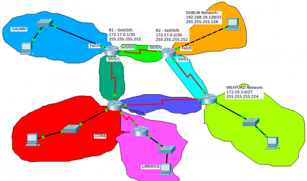
- R 192.19.3.0/27 [120/2] via 172.17.0.2, 00:00:26, Serial0/0/0
- R: RIP - Protocol used to generate this route.
- C: Directly connected network
- S: Static - Ruta ingresada manualmente (Static routing)
- 192.19.3.0/27: Netword Destination address and Netmask
- via 172.17.0.2: This is the IP Adress of the interface of the Router attached through which the network can be reached.
- Gateway or Next hop: it points to the gateway through which the network can be reached.
- Serial0/0/0 is the interface of the current Router that is attached to the gateway. That is, Serial0/0/0 is connected to 172.17.0.2
- 120: is the Administrative Distance
Static routing
Dynamic routing
Many IP routing protocols exist. However, they all have some core features in common:
- Learn routing information about IP subnets from other neighboring routers (discovery of remote networks).
- If a router learns of more than one router to reach one subnet, choose the best route based on that routing protocol’s concept of a metric (choose the best path)
- React to changes when the network topology changes e.g. when a link fails, and converge to use a new choice of best route for each destination subnet.
- Advertise routing information about IP subnets to other neighboring routers.
Routing Table Structure:
- A directly connected network is a network that is directly attached to one of the router interfaces.
- When a router interface is configured with an IP address and subnet mask, the interface becomes a host on that attached network.
- The network address and subnet mask of the interface, along with the interface type and number, are entered into the routing table as a directly connected network.
- When a router forwards a packet to a host, such as a web server, that host is on the same network as a router's directly connected network.
- A remote network is a network that is not directly connected to the router.
- Remote networks are added to the routing table using either a dynamic routing protocol or by configuring static routes.
- The network/exit-interface is the address of the local interface or the interface name that is in that network.
Example of routing protocols
- RIP (Routing Information Protocol)
- EIGRP (Enhanced Interior Gateway Routing Protocol)
- OSPF (Open Shortest Path First)
EIGRP is a Cisco proprietary routing protocol, whereas all other routing protocols listed are standard, non-proprietary protocols.
Administrative Distance (AD)
In some cases, internetworks use Multiple Routing Protocols. In such cases, a router learns of multiple routes to a particular subnet using different routing protocols. Which will be used? AD is used to rank routing protocols. AD is an integer from 0 to 255 that rates the trustworthiness of the source of the IP routing information.
| Route Source | Administrative Distance |
|---|---|
| Connected routes | 0 |
| Static routes | 1 |
| OSPF | 110 |
| IS-IS | 115 |
| RIP (V1 and V2) | 120 |
| Unknown/Unbelievable | 255 |
Open Shortest Path First (OSPF)
- OSPF is a routing protocol for Internet Protocol (IP) networks. It uses a link state routing (LSR) algorithm and falls into the group of interior gateway protocols (IGPs)
- OSPF is a widely used IGP in large enterprise networks.
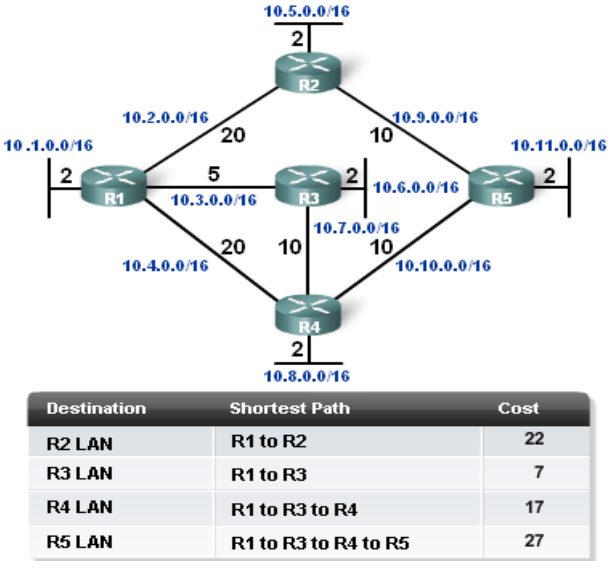
- Determining the shortest path:
- The shortest path to a destination is found by accumulating (adding) the calculated costs to the destination network.
- Once SPF has identified a route, OSPF calculates the metric for a route as follows: The sum of the OSPF interface costs for all outgoing interfaces in the route.
Ethernet
It's the the dominant Local Area Network (LAN) technology.
In the mid 1980s, the Institute of Electrical and Electronic Engineers (IEEE) published a formal standard for Ethernet, defined as the: IEEE 802.3 Standard.
Ethernet is not one networking technology, but a family of networking technologies that includes:
- Legacy, Fast Ethernet and
- Gigabit Ethernet
Over the years Ethernet has evolved and many different variations exist, many of these carried over different physical cables. This means that there are a number of different IEEE802.3 standards.
Ethernet standard spans the Physical and Data Link Layers: Referred to as a Layer Two Protocol
- The Media Access Control Layer is responsible for deciding when a host should transmit.
- The Logical Link Control Layer is responsible for setting up and controlling the link.
Ethernet Standards: Some startards are:
- 802.3u (Fast Ethernet)
- 802.3z (1000BASE-X Gbit/s Ethernet over Fiber-Optic at 1 Gbit/s)
Major categories of Ethernet have also been organized by their speed:
- Ethernet (10Mbps)
- Fast Ethernet (100Mbps)
- Gigabit Ethernet
- 10 Gigabit Ethernet
Ethernet II Frame (also known as DIX):
- Maximum frame size possible = 1518 bytes
- Minimum valid frame size = 64 bytes
Ethernet Types:
| Type | Value |
|---|---|
| IPv4 | 0800 |
| IPv6 | 86DD |
| VLAN | 8100 |
| ARP | 0806 |
Wireless networks
Wireless Technologies:
- PAN/WPAN (Personal Area Network (PAN)/wireless personal area network (WPAN)
- Bluetooth, IEEE 802.15.4
- LAN (Local Area Network)
- IEEE 802.11
- MAN (Metropolitan Area Network)
- IEEE 802.11, IEEE 802.16, IEEE 802.20
- WAN (Wide Area Network)
- GSM, CDMA, Satelite, 3G, LTE
Note que algunos de estos términos (notablemente LAN y WAN) son empleados no sólo en Wireless technologies. Podemos, por supuesto, hablar de Wired LAN or Wired WAN.
What wireless channel and frequency is a Network on
Using the software LinSSID, we performed a scan of the wireless networks in my house. In Figures are shown the results for 2.5GHz Channels. We can see our home network (iptime) is on channel 6 and its frequency is 2.437GHz:
XXXXXXXXXXXXXXXXXXX
What version of IP address do clients on the network receive fromt he ISP
- Where did you receive this IP address from?
In order to know what version of IP address receive clients on the network, we need to know the public IP address, which is the IP address provided for the ISP. The public IP address can be displays with a simple Google search.That is, entering “My IP address on our web search engine. There are many Web sites that are able to provide the public IP. In Fig. 3.4 is shown the result obtained in my case.The Linux command«curl»provide another way of knowing the public IP address:
curl ipinfo.io/ip
The results show that clients on the network receive IPv4 from the ISP.
Wireless LANs (WLANs)
A WLAN is a Wireless Local Area Network, which is the linking of two or more computers without using wires. Instead, radio waves and IEEE 802.11 are used to communicate.
WLANs use infrared light (IR) or radio frequencies (RFs). The use of RF is far more popular for its longer range, higher bandwidth, and wider coverage.
Wireless LAN have to operate in the ISM (Industrial Scientific Medical) band.
Wireless LANs Primarily operate in the 2.4Ghz (2.401 - 2.483) & 5Ghz (5.470 - 5.725) frequency ranges. Basically a Higher frequency result in a greater speed but in a shorter range. That means 5Ghz waves cannot travel such great distances as 2.4Ghz waves but can carry more data. Also, the 5Ghz frequency is shared with less other unlicenced equipment.
Because the wireless transmission medium is shared, it is not possible to transmit in the exact same frequency without collisions (interference). The solution is to devide the ISM band into channels and map each WLAN/SSID on a single channel.
The 2.4 GHz range is devided into 11 channels. Each channel of 22MHz bandwidth (because we need 22MHz to transmit 54 Mbps in 802.11g) y una separación de 5MHz entre cada channel.
The most common arrangement is to use only channels 1, 6, and 11, which do not overlap with each other at all.
The 5-GHz (U-NII) band is much more flexible in this regard because it has many more non-overlapping channels available. In fact, all channels are spaced such that they will not overlap each other. Each U-NII channel is 20 MHz wide. With all four U-NII bands set aside for wireless LANs, a total of 23 non-overlapping channels are available.
Wireless technologies
- PAN/WPAN (Personal Area Network (PAN)/ Wireless Personal Area Network (WPAN)
- Bluetooth, IEEE 802.15.4
- LAN (Local Area Network)
- IEEE 802.11
WLAN Components
- Wireless Client Receiver:
- It is needed to connect a computing device (e.g. desktop, laptop, PDA…) to the wired networked via an access point. It includes Onboard Cards (most laptops) PCMCIA, PCI card or USB adaptor
- Access points (APs):
- They are needed only in the Infrastructure Mode of WLANs. They provide the wireless client with a point of access into a network. They are like Ethernet switches in a wired network and operate in half-duplex mode (e.g. They either receive or transmit at any given time).
- Wireless repeater:
- A wireless repeater (also called wireless range extender) takes an existing signal from a wireless router or wireless access point and rebroadcasts it to create a second network. When two or more hosts have to be connected with one another over the IEEE 802.11 protocol and the distance is too long for a direct connection to be established, a wireless repeater is used to bridge the gap. The throughput for client devices will be low because each repeater must receive and re-transmit each packet.
- Wireless bridge:
- A wireless bridge is a device used for connecting two or more network separated physically, operating on the 802.11 standard.
The WLAN supports four Network Topologies
- Peer-to-peer (Ad hoc) Topology: An ad hoc network is a type of temporary computer-to-computer connection. In ad hoc mode, you can set up a wireless connection directly to another computer without having to connect to a Wi-Fi access point or router.
- Hybrid Topology:
- Infrastructure Topology: All devices are connected to an access point.
- Point-to-point Topology: When we have two different networks connected by a Wirelless bridge.
802.11 standards
802.11 is the generic name of a family of standards for wireless networking. The numbering system for 802.11 comes from the IEEE (a nonprofit professional organization), who uses “802” for many networking standards like Ethernet (802.3).
The 802 committee supports in this model the LLC (logical link control), the MAC (media access control) and PHY (physical layers).
Popular 802.11 standards include 802.11a, 802.11b, 802.1g, 802.11n, 802.11ac (Newest)
Some EEE 802.11 standards are:
| Standard | Release Date | Frequency band | Max speed (Data Rate) | Max range | Comments |
|---|---|---|---|---|---|
| 802.11 | 1997 | 2.4 GHz | 2 Mbps | Undefined | Legacy |
| 802.11a | 1999 | 5 GHz | 54 Mbps | 50m | Not compatible with b, g / Expensive / Modulation: OFDM |
| 802.11b | 1999 | 2.4 GHz | 11 Mbps | 100m | First 2.4 GHz Technology / Modulation: DSSS |
| 802.11g | 2003 | 2.4 GHz | 54 Mbps | 100m | Backward compatible with b / Shares range with b / Modulation: OFDM, DSSS |
| 802.11n | 2011 | 2.4 or 5 GHz | 600 Mbps | 300m | Modulation: OFDM |
| 802.11ac | 2014 | 5 GHz | 1.3 Gbps | 300m | Newest Standard |
Wireless Security
Why secure the WLAN?
- Firstly, if someone manages to hack into your WLAN, they are stealing your bandwidth.
- Worse, anyone on your WLAN will be using the same Internet protocol (IP) address as you. To others on the Internet they appear to be you.
What security can you get now?
- The first being to change the default settings of your Access point:
- The most important is the Extended Service Set Identification (ESSID) (Network Name)
- You can configure the AP so that it doesn't broadcast (para que no muestre) the ESSID.
- The Extended Service Set Identification (ESSID) is one of two types of Service Set Identification (SSID).
- An SSID is a 32-character (maximum) alphanumeric key identifying the name of the wireless local area network. Some vendors refer to the SSID as the network name. For the wireless devices in a network to communicate with each other, all devices must be configured with the same SSID.
- In an infrastructure wireless network that includes an access point, the ESSID is used, but may still be referred to as SSID.
- In an Ad hoc wireless network with no access points, the Basic Service Set Identification (BSSID) is used.
- MAC address filters:
- There's a second layer of security you can adopt, the MAC (Media Access Control) address filter. A MAC address is a unique identity burned into every network adapter during manufacture, with no way of changing it. Using this filter, the AP maintains a list of MAC addresses and only permits those on the list to connect.
- Encryption:
- Even if hackers can't get past your AP, they may still be able to access data that's traversing your WLAN.
- The way to protect data in transit is encryption, the original WLAN encryption standard was WEP (Wired Equivalence Privacy).
- WEP works by encrypting traffic -scrambling it- as it leaves the AP or client PC and decrypting it on arrival.
- WEP has been replaced by WPA (Wifi Protected Access).
- Disable remote access to the router administration GUI:
- Make sure you only configure the AP over a wired connection.
- To remotely log into your router's administrative console you just have to open a browser window and typing the router IP address.
- Your router is likely to have what is known as a non-routable internal IP address such as 192.168.1.1 or 10.0.0.1 as it's address
- Below are some of the standard admin interface addresses used by some of the more common wireless router manufacturers:
- Linksys - 192.168.1.1 or 192.168.0.1
- DLink - 192.168.0.1 or 10.0.0.1
- Apple - 10.0.1.1
- ASUS - 192.168.1.1
- Buffalo - 192.168.11.1
- Netgear - 192.168.0.1 or 192.168.0.227
- Choose a strong password for the router administration GUI:
- Routers usually come with an obvious default password (admin in many cases). Therefore, it is important to change it and choses a secure password to try to prevent someone from entering to the router administration GUI and change your network configurations.
- Choose a strong password for the wireless network
- Authentication
- The final layer of protection is individual authentication.
- The standard method of WLAN authentication uses the 802.1X protocol.
- If the protocol is enabled, unauthenticated users cannot get past the AP to access the rest of the network.
- Install a good firewall device to your router
Service set
https://en.wikipedia.org/wiki/Service_set_(802.11_network)
In IEEE 802.11 wireless local area networking standards, a service set is a group of wireless network devices that are operating with the same networking parameters.
Service sets are arranged hierarchically,: Basic Service Sets (BSS) are units of devices operating with the same medium access characteristics (i.e. radio frequency, modulation scheme etc), while Extended Service Sets (ESS) are logical units of one or more basic service sets on the same logical network segment (i.e. IP subnet, VLAN etc). There are two classes of basic service sets: those that are formed by infrastructure mode redistribution points (access points or mesh nodes), and those that are formed by independent stations in a peer-to-peer ad hoc topology. Basic service sets are identified by BSSIDs, which are 48-bit labels that conform to MAC-48 conventions. Logical networks (including extended service sets) are identified by SSIDs, which serve as "network names" and are typically natural language labels.
Wireless mobile networks
Para ver las características de las tarjetas de red (network card)
http://www.linuxnix.com/find-network-cardwiredwireless-details-in-linuxunix/
Tales como: Name of network cards, Network card link status, Network card speeds, Network card MAC address, Network card IP address, Network card driver details, Network card manufacture details, Network card duplex/half duplex details, Network card auto-negotiation details, Complete network card capabilities details, Complete network card hardware details
sudo lshw -c network
DHCP
Media:DHCP-Lecture_Greg2018.pdf
DNS
Media:Introduction_to_DNS-Lecture_Greg2018 .pdf
Media:DNS-Lecture_Greg2018.pdf
Observing DNS Resolution: Media:Lab-Observing_DNS_Resolution.pdf
- Part 1: Observe the DNS Conversion of a URL to an IP Address
- Part 2: Observe DNS Lookup Using the nslookup Command on a Web Site
- Part 3: Observe DNS Lookup Using the nslookup Command on Mail Servers
Using Wireshark to observe traffic
Media:4-2-Using Wireshark to observe the DHCP process.pdf
Media:7-3-Using_Wireshark_to_Examine_a_UDP_DNS_Capture.pdf
Campus LAN and Wireless LAN Design Guide - Cisco
File:Campus-LAN-WLAN-Design-Cisco.pdf
Campus Wired LAN Design Fundamentals
The LAN is the networking infrastructure that provides access to network communication services and resources for end users and devices spread over a single floor or building. You create a campus network by interconnecting a group of LANs that are spread over a small geographic area. Campus network design concepts are inclusive small networks that use a single LAN switch, up to very large networks with thousands of connections.
The campus wired LAN enables communications between devices in a building or group of buildings, as well as interconnection to the WAN and Internet edge at the network core.
Hierarchical design model
The campus wired LAN uses a hierarchical design model to break the design up into modular groups or layers. Breaking the design up into layers allows each layer to implement specific functions, which simplifies the network design and therefore the deployment and management of the network
Modularity in network design allows you to create design elements that can be replicated throughout the network. Replication provides an easy way to scale the network as well as a consistent deployment method.
In flat or meshed network architectures, changes tend to affect a large number of systems. Hierarchical de-sign helps constrain operational changes to a subset of the network, which makes it easy to manage as well as improve resiliency. Modular structuring of the network into small, easy-to-understand elements also facilitates resiliency via improved fault isolation.
A hierarchical LAN design includes the following three layers:
- Access layer: Provides endpoints and users direct access to the network
- Distribution layer: Aggregates access layers and provides connectivity to services
- Core layer: Provides connectivity between distribution layers for large LAN environments
Depending on the characteristics of the deployment site, you might need one, two, or all three of the layers. For example:
- A site that occupies a single building might only require the access and distribution layers,
- While a campus of multiple buildings will most likely require all three layers.
Regardless of how many layers are implemented at a location, the modularity of this design ensures that each layer will provide the same services, and in this architecture, will use the same design methods:
Access layer
The access layer is where user-controlled devices, user-accessible devices, and other end-point devices are connected to the network. The access layer provides both wired and wireless connectivity and contains features and services that ensure security and resiliency for the entire network.
- Device connectivity: ...
- Resiliency and security services: ...
- Advanced technology capabilities: ...
Distribution layer
The distribution layer supports many important services. In a network where connectivity needs to traverse the LAN end-to-end, whether between different access layer devices or from an access layer device to the WAN, the distribution layer facilitates this connectivity.
- Scalability: At any site with more than two or three access-layer devices, it is impractical to interconnect all access switches. The distribution layer serves as an aggregation point for multiple access-layer switches.
- The distribution layer can lower operating costs by making the network more efficient, by requiring less memory, by creating fault domains that compartmentalize failures or network changes, and by processing resources for devices elsewhere in the network. The distribution layer also increases network availability by containing failures to smaller domains.
- Reduce complexity and increase resiliency: The campus wired LAN has the option to use a simplified distribution layer, in which a distribution-layer node consists of a single logical entity that can be implemented using a pair of physically separate switches operating as one device or using a physical stack of switches operating as one device. Resiliency is provided by physically redundant components like power supplies, supervisors, and modules, as well as stateful switchover to redundant logical control planes.
- This approach reduces complexity of configuring and operating the distribution layer because fewer proto-cols are required. Little or no tuning is needed to provide near-second or sub-second convergence around failures or disruptions.
Two-Tier Design
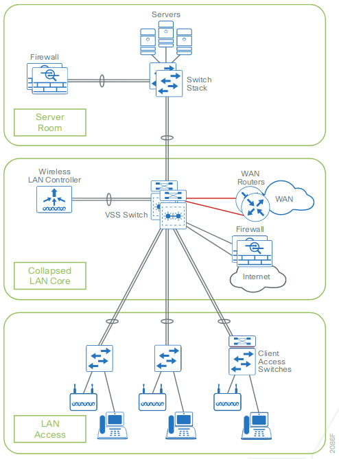
In an Two-Tier Design, the distribution layer provides connectivity to network-based services, to the WAN, and to the Internet edge. Network-based services can include and are not limited to Wide Area Application Services (WAAS) and WLAN controllers. Depending on the size of the LAN, these services and the interconnection to the WAN and Internet edge may reside on a distribution layer switch that also aggregates the LAN access-layer connectivity. This is also referred to as a collapsed core design because the distribution serves as the Layer 3 aggregation layer for all devices.
Three-Tier Design
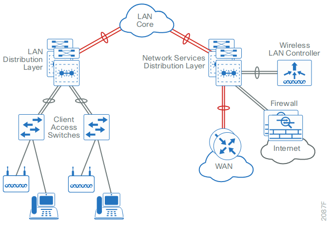
Larger LAN designs require a dedicated distribution layer for network-based services versus sharing connectivity with access layer devices. As the density of WAN routers, WAAS controllers, Internet edge devices, and WLAN controllers grows, the ability to connect to a single distribution layer switch becomes hard to manage. There are a number of factors that drive LAN design with multiple distribution layer modules:
- The number of ports and port bandwidth that the distribution layer platform can provide affects network performance and throughput.
Network resilience is a factor when all LAN and network-based services rely on a single platform, regardless of that platform's design, it can present a single point of failure or an unacceptably large failure domain.
- Change control and frequency affects resilience. When all LAN, WAN, and other network services are consolidated on a single distribution layer, operational or configuration errors can affect all network operation.
- Geographic dispersion of the LAN access switches across many buildings in a larger campus facility would require more fiber optic interconnects back to a single collapsed core.
Like the access layer, the distribution layer also provides quality of service (QoS) for application flows to guarantee critical applications and multimedia applications perform as designed.
Core layer
In a large LAN environment, there often arises a need to have multiple distribution layer switches.
- One reason for this is that when access layer switches are located in multiple geographically dispersed buildings, you can save potentially costly fiber-optic runs between buildings by locating a distribution layer switch in each of those buildings.
- As networks grow beyond three distribution layers in a single location, organizations should use a core layer to optimize the design.
- Another reason to use multiple distribution layer switches is when the number of access layer switches connecting to a single distribution layer exceeds the performance goals of the network designer. In a modular and scalable design, you can collocate distribution layers for data center, WAN connectivity, or Internet edge services.
- In environments where multiple distribution layer switches exist in close proximity and where fiber optics provide the ability for high-bandwidth interconnect, a core layer reduces the network complexity, from N * (N-1) to N links for N distributions, as shown in the following two figures.
- The core layer of the LAN is a critical part of the scalable network, and yet it is one of the simplest by design. The distribution layer provides the fault and control domains, and the core represents the 24x7x365 nonstop connectivity between them, which organizations must have in the modern business environment where connectivity to resources to conduct business is critical. Connectivity to and from the core is Layer 3-only, which drives increased resiliency and stability.
Campus wired network design options
When you scale from a single switch in a campus LAN up to a full three-tier campus network, the reliability of the network is increasingly important, because network downtime likely affects a greater user population with a larger workplace and economic significance. To mitigate the concerns about unavailability of network resources, campus designs include additional resiliency options, such as redundant links, switches, and switch components. In traditional multilayer campus designs, the added resiliency comes at a cost of configuration complexity, with most of the complexity introduced from the interaction of the access and aggregation layers of the campus LAN.
The primary function of the distribution layer is to aggregate access layer switches in a given building or cam-pus. The distribution layer provides a boundary between the Layer 2 domain of the access layer and the Layer 3 domain that provides a path to the rest of the network. This boundary provides two key functions for the LAN. On the Layer 2 side, the distribution layer creates a boundary for spanning tree protocol (STP), limiting propaga-tion of Layer 2 faults. On the Layer 3 side, the distribution layer provides a logical point to summarize IP routing information when it enters the network. The summarization reduces IP route tables for easier troubleshooting and reduces protocol overhead for faster recovery from failures.
Traditional Multilayer Campus Distribution Layer Design
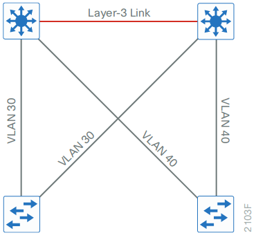
Traditional LAN designs use a multi-tier approach with Layer 2 from the access layer to the distribution layer, where the Layer 3 boundary exists. The connectivity from the access layer to the distribution layer can result in either a loop-free or looped design.
In the traditional network design, the distribution layer has two standalone switches for resiliency. It is recommended that you restrict a Layer 2 virtual LAN (VLAN) to a single wiring closet or access uplink pair in order to reduce or eliminate topology loops that STP must block and that are a common point of failure in LANs. Restricting a VLAN to a single switch provides a loop-free design, but it does limit network flexibility.
To create a resilient IP gateway for VLANs in the traditional design, you must use first-hop redundancy protocols, which provide hosts with a consistent MAC address and gateway IP for a VLAN. Hot standby routing protocol (HSRP) and virtual router redundancy protocol (VRRP) are the most common gateway redundancy protocols, but they only allow hosts to send data out one of the access uplinks to the distribution layer and require additional configuration for each aggregation switch in order to allow you to distribute VLANs across uplinks. Gateway load-balancing protocol (GLBP) does provide greater uplink utilization for traffic exiting the access layer by balancing load from hosts across multiple uplinks, but you can only use it in a non-looped topology.
All of these redundancy protocols require that you fine-tune the default timer settings in order to allow for sub-second network convergence, which can impact switch CPU resources.
Some organizations require the same Layer 2 VLAN be extended to multiple access layer closets to accom-modate an application or service. The looped design causes spanning tree to block links, which reduces the bandwidth from the rest of the network and can cause slower network convergence. The inefficiencies and the increased potential for misconfiguration drive network engineers to look for more appealing alternatives.
Routed Access Layer to Distribution Design
In another approach to access and distribution layer design, you can use Layer 3 all the way to the access layer. The benefits of this design are that you eliminate spanning tree loops and reduce protocols because the IP gateway is now the access switch. Because there are no spanning-tree blocking links, you can use both uplinks to the access layer and increase effective bandwidth available to the users.
The challenge with the routed access layer design is that the Layer 2 domains are confined to a single access closet, which limits flexibility for applications that require Layer 2 connectivity that extends across multiple access closets.
Campus Fabric Design
You can overcome the Layer 2 limitations of the routed access layer design by adding campus fabric capability to the Layer 3 access network. The campus fabric design enables the use of virtual networks (overlay networks) running on a physical network (underlay network) in order to create alternative topologies to connect devices. In addition to network virtualization, campus fabric allows for software-defined segmentation and policy enforce-ment based on user identity and group membership, integrated with Cisco TrustSec technology. For additional information, visit cisco.com and search for Campus Fabric
Simplified Distribution Layer Design
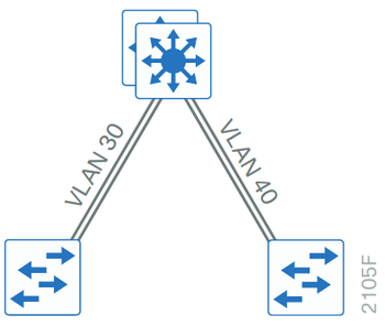
An alternative that can handle Layer 2 access requirements and avoid the complexity of the traditional multi-layer campus is called a simplified distribution layer design. The design uses multiple physical switches that act as a single logical switch, such as switch stack or a VSS, or the less preferred single, highly-redundant physi-cal switch. One advantage of this design is that spanning tree dependence is minimized, and all uplinks from the access layer to the distribution are active and passing traffic. Even in the distributed VLAN design, you eliminate spanning tree blocked links because of looped topologies. You reduce dependence on spanning tree by using EtherChannel to the access layer with dual-homed uplinks. This is a key characteristic of this design, and you can load-balance up to eight links if needed for additional bandwidth. At the same time, multiple links in an Ether-Channel have better performance characteristics versus single independent links.
EtherChannel is a logical interface that can use a control plane protocol to manage the physical members of the bundle. It is better to run a channel protocol instead of using forced-on mode because a channel protocol per-forms consistency checks for interfaces programmed to be in the channel and provides protection to the system from inconsistent configurations. Cisco Catalyst switches provide both port aggregation protocol (PAgP), which is a widely deployed Cisco designed protocol, and link aggregation protocol (LACP), which is based on IEEE 802.3ad.
There are several other advantages to the simplified distribution layer design. You no longer need IP gateway redundancy protocols such as HSRP, VRRP, and GLBP, because the default IP gateway is now on a single logical interface and resiliency is provided by the distribution layer switch or switches. Also, the network will converge faster now that it is not depending on spanning tree to unblock links when a failure occurs, because EtherChannel provides fast sub-second failover between links in an uplink bundle.
The topology of the network from the distribution layer to the access layer is logically a hub-and-spoke topology, which reduces complexity of design and troubleshooting. The hub-and-spoke topology design provides a more efficient operation for IP Multicast in the distribution layer because there is now a single logical designated router to forward IP Multicast packets to a given VLAN in the access layer.
Finally, by using the single logical distribution layer design, there are fewer boxes to manage, which reduces the amount of time spent on ongoing provisioning and maintenance.
Network Simulation using PacketTracer


